From Spatial Capture to Design Intent: The Professional Scan-to-CAD Workflow
The transition from a physical asset to a functional digital twin is a cornerstone of modern engineering and design. Utilizing high-fidelity mobile scanning, such as the technology integrated into the Structure Platform, allows professionals to bridge the gap between reality and digital simulation with unprecedented speed. But what if your projects require a CAD (Computer Aided Design) file.
Sensors produce meshes, clouds of points joined by a texture that represents a 3D object. They’re easy to store and easy to work with. But some projects require CAD files, which are made entirely out of math. A cube in a Cad file isn’t several hundred points, but a formula representing a cube - it can’t lose resolution, and a must for certain design tasks, like working with CCM machines.
So how do you bridge the gap? You formalize your mesh using the Scan-to-CAD process is not about correcting errors — translating high-resolution spatial captures into parametric models that are required for certain types of manufacturing and iterative design.
Phase 1: Data Acquisition (The Point Cloud)
The workflow begins with the capture of high-density spatial data. Using the Structure Sensor, practitioners capture the exact geometry of an object.
- The Process: As the scanner orbits the object, it generates a Point Cloud—a high-fidelity dataset consisting of millions of precise (X,Y,Z) coordinates.
- The Value: This is the primary layer of your digital twin. It provides a comprehensive, accurate spatial record of the object's current state in three-dimensional space.
Phase 2: Surface Representation (Polygonal Mesh)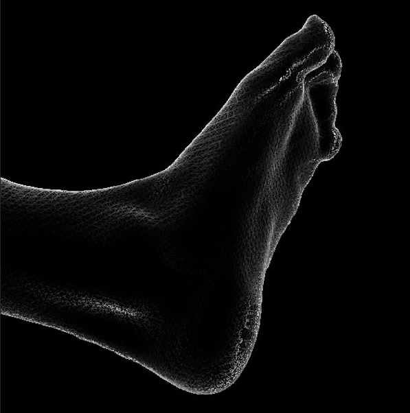
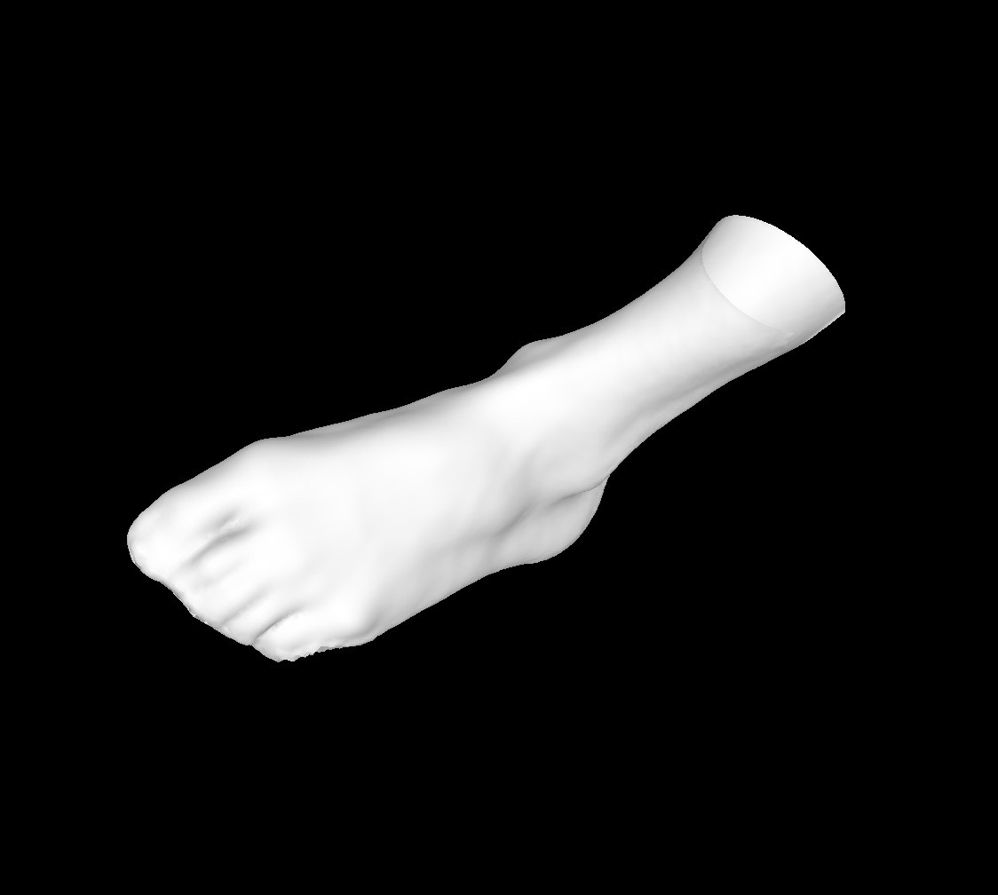
Once the point cloud is captured, the software processes these coordinates into a Mesh. By connecting the points with a network of vertices and edges, the raw data is transformed into a continuous surface.
- The Format: This is typically exported as an STL or OBJ file, which are printable files for consumer 3D printers.
- The Function: The Mesh provides a highly detailed geometric "shell." The mesh represents the surface of the object, suitable for visualization, simulation, and initial spatial analysis.
Phase 3: Parametric Optimization (The CAD Transition)
The most critical stage of the workflow is the transition from a mesh to a Parametric CAD Model. This is where the digital twin gains "intelligence." Rather than "fixing" the scan, this stage involves extracting design intent from the captured data.
- Feature Extraction: Engineers use the scan as a high-precision reference template to define geometric primitives—such as cylinders, planes, and complex lofted surfaces—with mathematical exactness.
- Parametric Intelligence: By converting the mesh into a Solid Body, the model becomes editable through dimensions and constraints. If a component requires a structural adjustment, the change is made through precise numerical input, ensuring the model remains mathematically sound.
- Alignment & Deviation: The CAD model is aligned to the scan data to ensure total fidelity. A Deviation Check is performed not to find "errors," but to validate that the formalized CAD model perfectly aligns with the real-world dimensions captured by the sensor.
Phase 4: The Milestone (The Golden File)
The final output is a professional-grade STEP or IGES file. This file represents the "Golden Version" of the digital twin, optimized for the following:
- Manufacturing Readiness: The file is fully compatible with CNC machining, injection molding, and high-precision 3D printing.
- Interoperability: The model can be integrated into larger assemblies, subjected to Finite Element Analysis (FEA), or used for computational fluid dynamics (CFD).
- Lifecycle Management: This CAD model serves as the permanent digital record for the asset’s entire lifecycle.
Professional Toolkit Recommendations
To maintain a seamless Scan-to-CAD pipeline, we recommend the following professional-grade tools:
- For Capture: Structure Capture. Engineered specifically for the Structure Sensor, this application ensures the highest level of data integrity during the initial acquisition phase.
- For Data Refinement: Autodesk Meshmixer. An essential tool for optimizing mesh density and preparing the polygonal data for seamless import into design environments.
- For Parametric Modeling: Autodesk Fusion 360. The industry standard for reverse engineering, allowing users to leverage mesh data to build robust, manufacturable solid bodies.
The Professional Perspective: A 3D scan is a high-fidelity map of reality. The Scan-to-CAD process is the methodology used to give that map professional utility. By treating your initial scan as a comprehensive reference, you provide your CAD environment with the highest quality data possible, ensuring that your final digital twin is both accurate and actionable.